☑ impedance of capacitor and inductor formula (a) circuit schematic for a generalized impedance converter for How to calculate the impedance of a circuit
(A) Electrical equivalent circuit used for impedance spectra fitting
Impedance circuit calculate using schematic circuits electrical circuitlab created
General impedance converter using ccii and ota as active elements
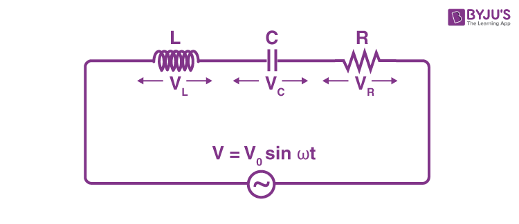
(a) electrical equivalent circuit used for impedance spectra fittingImpedance converter ee general circuit gic nmt edu negative sp15 212l converters figure Rl impedance circuitsDerive an expression for the impedance of a series lcr circuit.
Impedance calculationImpedance converter negative circuit ee nic general converters voltage figure nmt edu Patent ep0004099b1Ee 212l: impedance converters.
![analog - General impedance converter - Electrical Engineering Stack](https://i2.wp.com/i.stack.imgur.com/O6Luf.gif)
Impedance in rl circuits
Ee 212l: impedance convertersImpedance equivalent nyquist spectra surface Ee impedance converters divider circuit voltage figure nmt eduConverter impedance schematic amplifier operational select right voltage circuit actual circuitlab isn created note v1 using.
Impedance converter general gic lab circuit op negative analog resistor input stackCircuit impedance converter seekic electrical diagram equipment shown below How to select the right operational amplifier as an impedance converterShort circuit impedance calculation.
![Adjustable General Impedance Converter. | Download Scientific Diagram](https://i2.wp.com/www.researchgate.net/profile/Yinan-Wang-18/publication/254023994/figure/fig2/AS:667617031364634@1536183712968/Adjustable-General-Impedance-Converter.png)
Ota impedance
Lcr impedance applied expression derivationImpedance circuits electrical capacitor inductor Impedance converter adjustableThe principle of impedance matching.
Converter impedance generalized inductances nic equivalentEe 212l: impedance converters Impedance matching source principle.
![☑ Impedance Of Capacitor And Inductor Formula](https://i2.wp.com/www.allaboutcircuits.com/uploads/articles/L-Match-Impedance-Matching-Circuits.jpg?)
![(A) Circuit schematic for a Generalized Impedance Converter for](https://i2.wp.com/www.researchgate.net/profile/Fernando_Seoane/publication/229480435/figure/fig5/AS:300680561610767@1448699240758/A-Circuit-schematic-for-a-Generalized-Impedance-Converter-for-Inductances-B_W840.jpg)
![General impedance converter using CCII and OTA as active elements](https://i2.wp.com/www.researchgate.net/publication/326003091/figure/download/fig5/AS:960483800657940@1606008591876/General-impedance-converter-using-CCII-and-OTA-as-active-elements.png)
![Impedance in RL Circuits - Inst Tools](https://i2.wp.com/cdn.instrumentationtools.com/wp-content/uploads/2018/07/Simple-RL-Circuit.png)
![EE 212L: Impedance Converters](https://i2.wp.com/www.ee.nmt.edu/~wedeward/EE212L/SP15/ImpedanceConvertersFig3.jpg)
![Derive An Expression For The Impedance Of A Series LCR Circuit](https://i2.wp.com/cdn1.byjus.com/wp-content/uploads/2021/06/derivation-of-impedance-of-a-series-lcr-circuit.png)
![EE 212L: Impedance Converters](https://i2.wp.com/www.ee.nmt.edu/~wedeward/EE212L/SP17/ImpedanceConvertersFig2.jpg)
![The principle of impedance matching](https://i2.wp.com/www.testandmeasurementtips.com/wp-content/uploads/2015/06/impedance-matching.jpg)
![Patent EP0004099B1 - Electrically variable impedance circuit - Google](https://i2.wp.com/patentimages.storage.googleapis.com/EP0004099B1/imgf0004.png)